

Schematic of instrument
1. Laser, 2. Beam expander 3. Beam splitter assembly, 4. Whiteboard 5. Dial disk, 6. Battery box
 Principle of vision correction
Features
47 experimental demos
Cost effective solution
Detailed instructional manual
Easy alignment
Introduction
The LEOK-7 Laser Optical Demonstration Instrument is an affordable, versatile solution for optical education at universities and colleges. Designed for lower-class optical education, this kit provides a complete set of optical components and a light source, making it ideal for demonstrating fundamental optical principles in a hands-on environment.
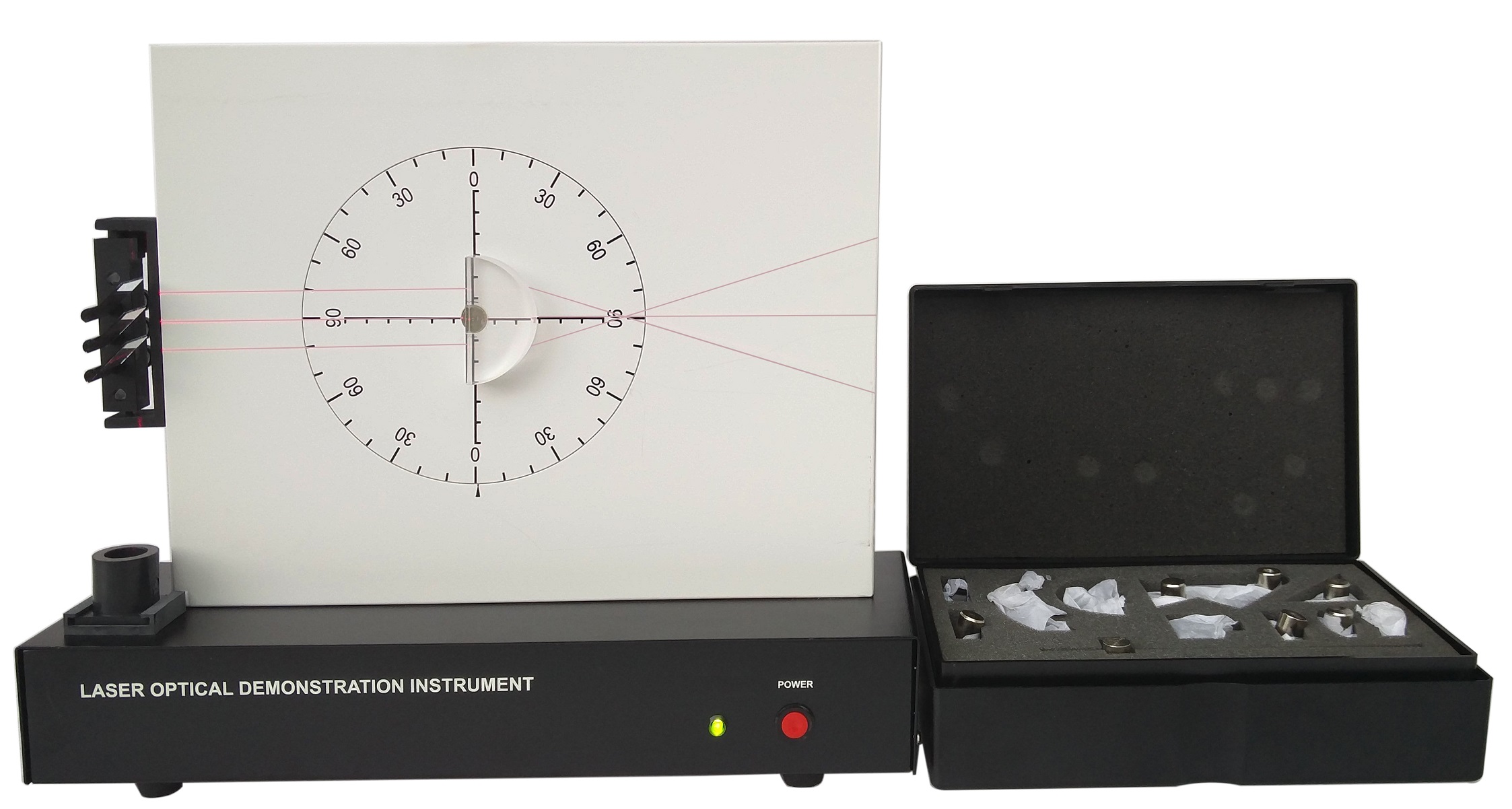
At the heart of the LEOK-7 is a diode laser that emits a beam, which is then expanded using a cylindrical lens. The beam is further split into three equally intense beams using a beam splitter assembly. These beams can be adjusted independently, allowing them to be viewed on a whiteboard for real-time demonstration of various optical phenomena. The system also includes a rotational disk with angular scales, allowing for precise alignment of optical components and demonstrations. This kit can be used for an extensive range of experiments across ray optics, imaging optics, and optical instruments. With the LEOK-7, students can directly observe light behavior, solidifying their understanding of optical principles. A list of 47 experimental demos can be conducted as follows: | |
1. Rectilinear propagation of light rays 2. Independent propagation of light rays 3. Law of light reflection 4. Beam expansion by a convex lens 5. Beam expansion by a cylindrical lens 6. Beam splitting by a beam splitter 7. Light reflection at a boundary of two media 8. Real image formed by convergent rays 9. Virtual image formed by divergent rays 10. Beam deflection by plane mirror 11. Imaging properties of a double mirror 12. Diffuse reflection of light 13. Law of light refraction 14. Total internal reflection of light 15. Applications of total internal reflection 16. Principle of periscope 17. Minimum deviation angle of prism 18. Displacement of rays through a parallel plate 19. Propagation of light through optical fiber 20. Convergence of light by concave mirror 21. Self-tracing of light by concave mirror 22. Imaging of concave mirror (object distance >2f') 23. Imaging of concave mirror (object distance f'~2f') 24. Imaging of concave mirror (object at focal plane) |
25. Imaging of concave mirror (distance < f') 26. Divergence of light by convex mirror 27. Self-tracing of light by convex mirror 28. Imaging of convex mirror 29. Rays passing nodal point of convex lens 30. Demonstrating focal point in object space 31. Light focusing by a convex lens 32. Principle of camera 33. Reversed imaging of unit magnification 34. Principle of projector 35. Principle of collimator 36. Principle of magnifier 37. Imaging of convex lens 38. Imaging of convex lens 39. Imaging of convex lens 40. Imaging of convex lens 41. Imaging of convex lens 42. Divergence of light by concave lens 43. Imaging of prism 44. Principle of Galilean telescope 45. Imaging of Galilean telescope 46. Principle of nearsighted vision correction 47. Principle of farsighted vision correction |
*Please click to view some sample pages of the instruction manual.
Part List
| Main unit | Incl a diode laser (powered by 3 AA batteries), beam expander, beam splitter, whiteboard, dial disk, etc. | |
Accessories | Right angle prism | Double plane mirror |
| Equilateral prism | Semi-cylindrical lens | |
| Concave-convex cylindrical mirror | Beam expander lens | |
| Diffuse reflector | Plastic optic fiber | |
| Plane parallel plate | Plane mirror | |
| Bi-convex cylindrical lens | Plano-concave cylindrical lens | |
| Galilean telescope | Periscope | |
| Plano-convex cylindrical lens | PDF manual | |
Schematic of instrument
1. Laser, 2. Beam expander 3. Beam splitter assembly, 4. Whiteboard 5. Dial disk, 6. Battery box
Principle of vision correction
