

Standing wave measurement
(Click figure to enlarge)

Standing wave distribution in cavity
(Click figure to enlarge)

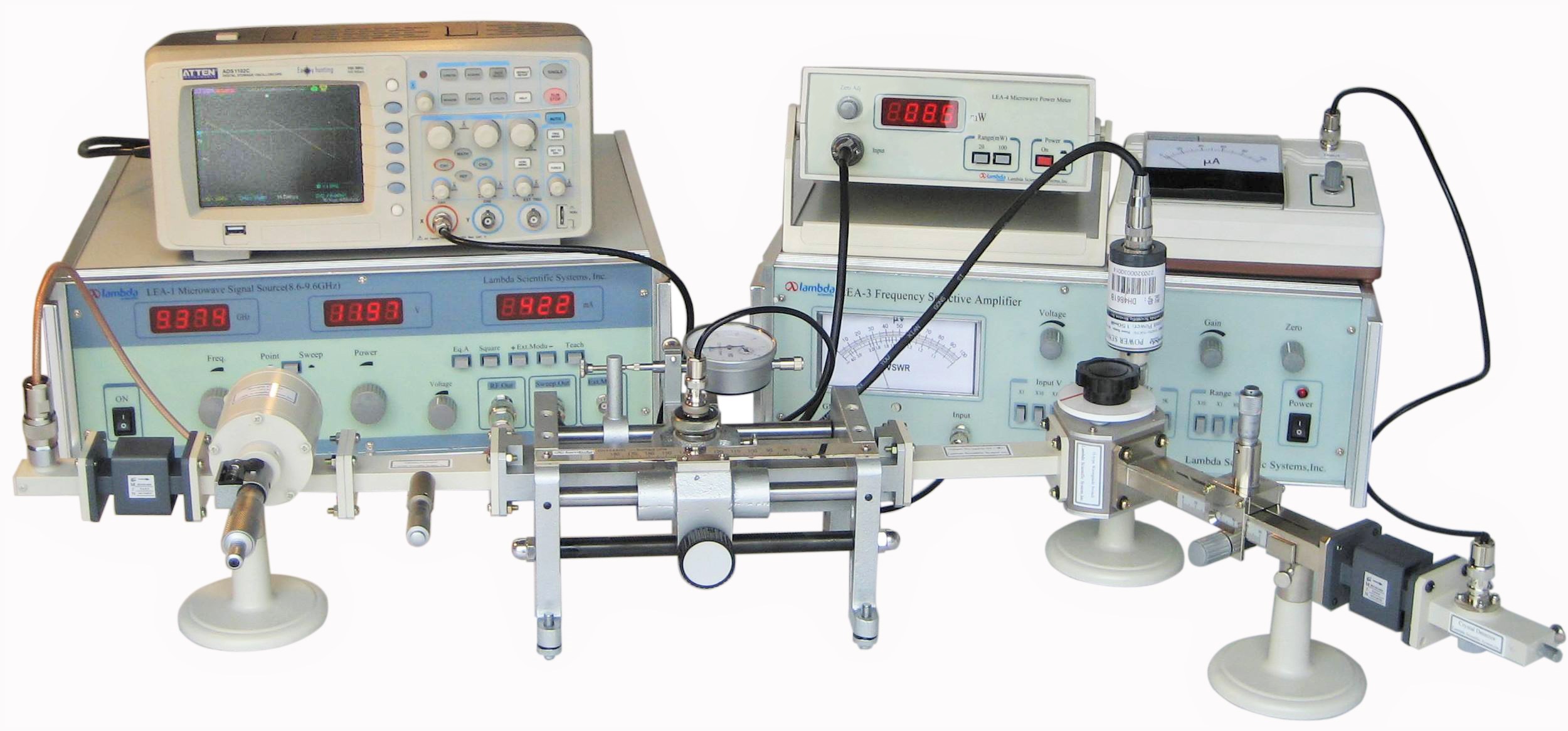
Microwave power measurement
(Click figure to enlarge)

Resonance curve with sample in cavity
(Click figure to enlarge)

Waveguide wavelength measurement
(Click figure to enlarge)

Measurement of ε and tan(δ) of media
(Click figure to enlarge)
Note: oscilloscope not included
Features
Comprehensive microwave waveguide experiments
Various waveguide components
High quality microwave devices
Dielectric material samples included
Introduction
The LEAI-65 Microwave and Waveguide Experimental System is a comprehensive tool designed to provide hands-on experience in measuring and analyzing various microwave parameters. Ideal for teaching modern physics and electrical engineering concepts, this system is specifically tailored for college and university laboratories. It features a set of microwave waveguide components operating at a three-centimeter wavelength, enabling students to conduct a range of experiments related to microwave propagation and measurement.
The instruction manual accompanying the system includes detailed information on experimental configurations, the underlying principles, and step-by-step instructions, allowing instructors to easily guide students through the experiments. Please click Experiment Contents to find more information about this apparatus. The system is designed for flexibility, allowing for various experiment setups through the selection of appropriate components. These experiments include (some experiments need to use the optional Precision variable attenuator) :
1. Learn to Use Microwave Devices and Components:
Students will gain hands-on experience with essential microwave devices and components, such as waveguides, power meters, and frequency meters, which are used to analyze and measure microwaves in practical settings.
2. Understand Microwave Work States and Transmission Characteristics:
Students will explore the transmission characteristics of microwaves as they propagate through waveguides. They will also investigate the different work states of microwaves and how they interact with materials and structures, contributing to a deeper understanding of waveguide technology.
3. Understand Field Properties of Microwave Transmission Paths:
The system allows students to study the field properties of microwaves as they travel through transmission paths, such as the way electromagnetic fields behave within the waveguide, and how they affect the transmission efficiency and power.
4. Measure Standing Wave, Attenuation, Wavelength (Frequency), and Power:
Students can measure key microwave parameters, including standing waves, attenuation, wavelength (and related frequency), and power levels. These measurements will give students insight into the behavior of microwaves as they propagate through different materials and conditions.
5. Measure Permittivity and Loss Tangent of Dielectric Materials:
An important aspect of the experiments is to measure the permittivity of dielectric materials using microwave transmission. Students will also learn to measure the loss tangent, which is critical for understanding how materials absorb and dissipate microwave energy.
Specifications
| Solid-state microwave signal source | |
| Frequency | range: 8.6 ~ 9.6 GHz; draft: ± 5×10⁻⁴/15 min; display error: ± 40 MHz |
| Output power | > 20 mW |
| Attenuation adjustment range | > 20 dB |
| Waveform | Equal amplitude |
| Internal modulation | square-wave; repetition frequency 1000 Hz |
| External modulation | polarity: +/-; amplitude: 5 ~ 40 VP-P; width: 0.2 ~ 3 μs; frequency: 300 ~ 3000 Hz |
| Narrow-band frequency scan | scan width: > 50 MHz; continuously adjustable |
| RF output connector | Type-N 50 Ω coaxial connector |
| Scan output | BNC connector, sawtooth wave output: 1 ~ 10 V |
| Slotted line measurement device | |
| Frequency range | 8.2 GHz ~ 12.4 GHz |
| Standing-wave coefficient | ≤ 1.03 (synthesis voltage) |
| Probe | travel: 95 mm; insertion depth: 1.5 mm |
| Frequency-selective amplifier | |
| Frequency range | 400 Hz ~ 10 kHz |
| Input voltage dynamic range | 10 μV ~ 2000 mV |
| Sensitivity | 10 μV (full scale) |
| Input impedance | 20 kΩ (1 kHz) |
| Centimeter wave power meter | |
| Frequency range | 8.6 GHz ~ 9.6 GHz |
| Power range | 100 μW ~ 100 mW |
| Microwave wavemeter | |
| Frequency range | 8.2 GHz ~ 12.4 GHz |
| Resolution | 0.005 GHz |
| Waveguides | |
| Cross section dimensions | inner: 22.86 mm × 10.16 mm (EIA: WR90 or IEC: R100) |
Parts List
| Description | Qty |
| Solid-state microwave signal source (@3 cm) | 1 |
| Slotted line measurement device (3 cm microwave) | 1 |
| Frequency-selective amplifier | 1 |
| Centimeter wave power meter | 1 |
| Variable attenuator | 1 |
| Wavelength meter | 1 |
| Detector | 1 |
| Cable | 1 |
| Detector display | 1 |
| Isolator | 2 |
| Circulator | 1 |
| Variable reactor | 1 |
| Single micrometer tuner | 1 |
| Straight waveguide | 1 |
| Matching load | 1 |
| Short-circuit plate | 1 |
| Resonant cavity | 1 |
| Coupler plate | 1 |
| Dielectric material sample | plastic glass, PTFE & black bakelite (3 pcs/ea) |
| Waveguide stand support | 3 |
| Screw | 40 |
| Instructional manual | 1 |
| Precision variable attenuator | 1 (option 1) |
| H-type 90 degree curve waveguide | 1 set (option 2) |
| H-type waveguide switch | |
| Straight waveguide (L=150) | |
| Directional coupler | |
| Mismatched load (VSWR 1.5 or 2.0) | |
| Mismatched load (VSWR 6-7) | |
| Passing through cavity |
Standing wave measurement
(Click figure to enlarge)
Standing wave distribution in cavity
(Click figure to enlarge)
Microwave power measurement
(Click figure to enlarge)
Resonance curve with sample in cavity
(Click figure to enlarge)
Waveguide wavelength measurement
(Click figure to enlarge)
Measurement of ε and tan(δ) of media
(Click figure to enlarge)
