

Schematic of transverse EO modulation
(Click figure to enlarge)

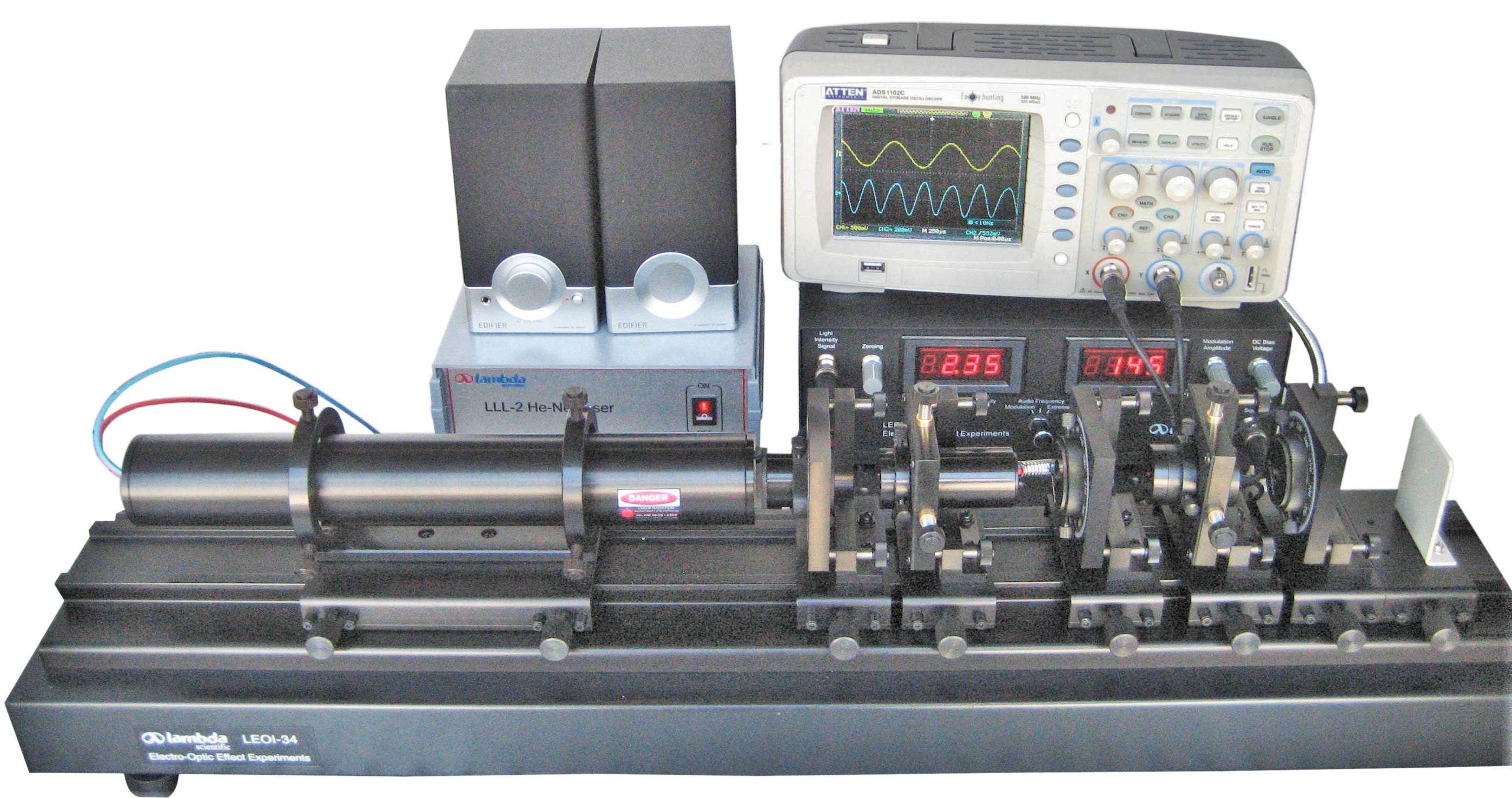
Schematic of experimental configuration
(Click figure to enlarge)

Effect of dc voltage bias on output characteristic of electro-optic crystal
(Click figure to enlarge)

Transmitted light intensity vs DC voltage
(Click figure to enlarge)

Linear and nonlinear modulation
Blue: input; Red: output
(Click figure to enlarge)
Note: oscilloscope not included
Features
Including He-Ne laser with power supply
Precise optical alignment
Observe and measure electro-optic modulation waveform
Electro-optic modulation technique demo
Introduction
The LEOI-34 Experimental System for Electro-Optic Modulation is designed to demonstrate the electro-optic effect in a crystal, where the refractive index of the material changes in response to an applied electric field. The system uses a LiNbO₃ (Lithium Niobate) crystal, known for exhibiting the Pockels effect (a linear electro-optic effect) and, to a lesser extent, the Kerr effect (a quadratic electro-optic effect).
The Pockels effect is the main phenomenon utilized in this apparatus, where the refractive index of the crystal changes linearly with the applied electric field. This effect allows for precise control over the polarization and intensity of light, making it a powerful tool in fields such as optical communication, modulation, and laser technology.
This system helps students understand the principles of the electro-optic effect, measure key parameters such as the half-wave voltage and electro-optic coefficient, and observe changes in the optical properties of the crystal under the influence of an electric field.
Using the LEOI-34 Experimental System for Electro-Optic Modulation, the following experiments can be conducted:
1. Electro-Optic Modulation Waveform:
Display and analyze the electro-optic modulation waveform, showing how the electric field modulates the light passing through the crystal.
2. Observation of Electro-Optic Modulation Phenomenon:
Observe the modulation phenomenon in the LiNbO₃ crystal under an applied electric field, demonstrating the interaction between the crystal's refractive index and the electric field.
3. Measurement of Half-Wave Voltage:
Measure the half-wave voltage of the electro-optic crystal, which is essential for understanding the required voltage to achieve full modulation of the light wave.
4. Calculation of Electro-Optic Coefficient:
Calculate the electro-optic coefficient, which is a measure of the sensitivity of the crystal’s refractive index to the applied electric field.
5. Demonstration of Optical Communication:
Demonstrate the use of electro-optic modulation in optical communication systems, showing how this technique is employed to modulate light for transmitting information.
The instruction manual contains comprehensive materials including experimental configurations, principles and step-by-step instructions. Please click Experiment Theory and Contents to find more information about this apparatus.
Specifications
| Power Supply for Electro-Optic Modulation | |
| Output Sine-Wave Modulation Amplitude | 0 ~ 300 V (Continuously Adjustable) |
| DC Offset Voltage Output | 0 ~ 600 V (Continuously Adjustable) |
| Output Frequency | 1 kHz |
| Electro-Optic Crystal (LiNbO3) | |
| Dimension | 5×2.5×60 mm |
| Electrodes | Silver Coating |
| Flatness | < λ/8 @633 nm |
| Transparent Wavelength Range | 420 ~ 5200 nm |
| He-Ne Laser | 1.0 ~ 1.5 mW @ 632.8 nm |
| Rotary Polarizer | Minimum Reading Scale: 1° |
| Photoreceiver | PIN Photocell |
Part List
| Description | Qty |
| Optical Rail | 1 |
| Electro-Optic Modulation Controller | 1 |
| Photoreceiver | 1 |
| He-Ne Laser (LLL-2) | 1 |
| Laser Holder (SZ-42) | 1 |
| LiNbO3 Crystal | 1 |
| BNC Cable | 2 |
| Four-Axis Adjustable Holder (SZ-24) | 2 |
| Rotary Holder (SZ-51) | 3 |
| Polarizer | 1 |
| Glan Prism | 1 |
| Quarter-Wave Plate | 1 |
| Alignment Aperture | 1 |
| Speaker | 1 |
| Ground Glass Screen | 1 |
Schematic of transverse EO modulation
(Click figure to enlarge)
Schematic of experimental configuration
(Click figure to enlarge)
Effect of dc voltage bias on output characteristic of electro-optic crystal
(Click figure to enlarge)
Transmitted light intensity vs DC voltage
(Click figure to enlarge)
Linear and nonlinear modulation
Blue: input; Red: output
(Click figure to enlarge)
