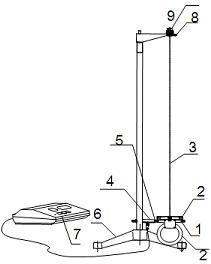
1. Claw
2. Rigid Ring
3. Specimen under Test
4. Hall Switch
5. Magnetic Steel
6. Base
7. Counting Timer
8. Indicator
9. Knob
Features
Hall sensor and electronic timer
Specially designed metal claw to replace traditional metal disk
High accuracy
Affordable
Introduction
The relationship between stress and strain within a material’s elastic limit is fundamental to understanding material behavior under load. This relationship is quantified using two critical parameters: (1) Young's Modulus: The ratio of longitudinal stress to strain, describing a material's stiffness under tensile or compressive forces, and (2) Shear Modulus: The ratio of shear stress to shear strain, which characterizes a material's response to shear deformation. Both Young's Modulus and Shear Modulus are widely applied in machinery, construction, transportation, and numerous other industrial fields.
The LEMI-17 Apparatus is specifically designed to measure the shear modulus and analyze the rotational moment of inertia (torsional pendulum) with exceptional precision. This innovative system features a specially engineered hanging claw, replacing traditional disk plates, to accommodate various rigid objects. These objects, such as rings, bars, or columns, can be mounted and rotated about the same axis in both horizontal and vertical orientations.
The advanced design ensures smooth torsional motion for accurate and repeatable results. A Hall switch with a magnet and digital timing device measures the torsional swing period. Half-period timing and optimal cycle determination enhance measurement accuracy.
With the LEMI-17 Apparatus, students can:
1. Measure and calculate the shear modulus of different materials.
2. Determine the rotational moment of inertia of rigid objects around different axes.
3. Validate the perpendicular and parallel axis theorems.
4. Investigate how shape, mass distribution, and axis orientation influence rotational dynamics.
The instruction manual provides detailed experimental setups and configurations, clear explanations of the underlying principles, step-by-step instructions for conducting experiments, and sample data and results for analysis and validation.
Please click Experiment Theory and Contents to find more information about this apparatus. Designed for physics and engineering laboratories, this apparatus combines precision, versatility, and ease of use, making it an invaluable tool for studying material properties and rotational mechanics.
Part List and Specifications
Item | Specifications | Qty |
| Digital timing device | Max counting number: 80; range: 0 ~ 255.99 s; resolution: 0.01 s | 1 |
| Hanging claw | Length: 110 mm; width: 16 mm; rigid ring mounted vertically or horizontally | 1 |
| Hall switch senor | DC 5 V | 1 |
| Support | Triangular base, and clamp on the support rod | 1 |
| Rigid ring | Inner diameter: 80 mm; outer diameter: 110 mm | 1 |
| Rigid square bar | Length 120 mm; mass ~ 312 g | 1 |
| Rigid column bar | Length 120 mm; mass ~ 187 g | 1 |
| Small steel ball | 2 | |
| Small magnetic steel | 1 | |
| String | Steel string and copper string, diameter ~ 0.4 mm, 5 each | 10 |

1. Claw
2. Rigid Ring
3. Specimen under Test
4. Hall Switch
5. Magnetic Steel
6. Base
7. Counting Timer
8. Indicator
9. Knob