

Schematic of an electronic scale circuit

Configurations of two measurement modes

Weighting sensor mass–voltage (m–U) curves under different bridge excitation voltages (half-bridge)

Relationship curve between slope K and bridge excitation voltage (half-bridge)
Features
Four individually accessible resistive strain gauges
Adjustable bridge excitation voltage
Simple structure and stable performance
Hands-on experiments
Introduction
The resistive strain gauge is a key sensing element used to measure mechanical strain. It functions by converting strain occurring in a mechanical structure into a change in electrical resistance. The core component of a weighting sensor is the resistive strain gauge, which is positioned at critical stress points within the sensor to detect deformation caused by weight variations.
Most commercial weighting sensors are equipped with four resistive strain gauges arranged in a full Wheatstone bridge configuration. This setup ensures both high sensitivity and good linearity. The voltage signal output from the bridge is then amplified and calibrated using a differential amplifier, allowing the resulting voltage (in mV or V) to correspond proportionally to the mass of the object being measured. This transformation enables the system to function as an electronic scale, where voltage readings can be interpreted in units of mass (g or kg).
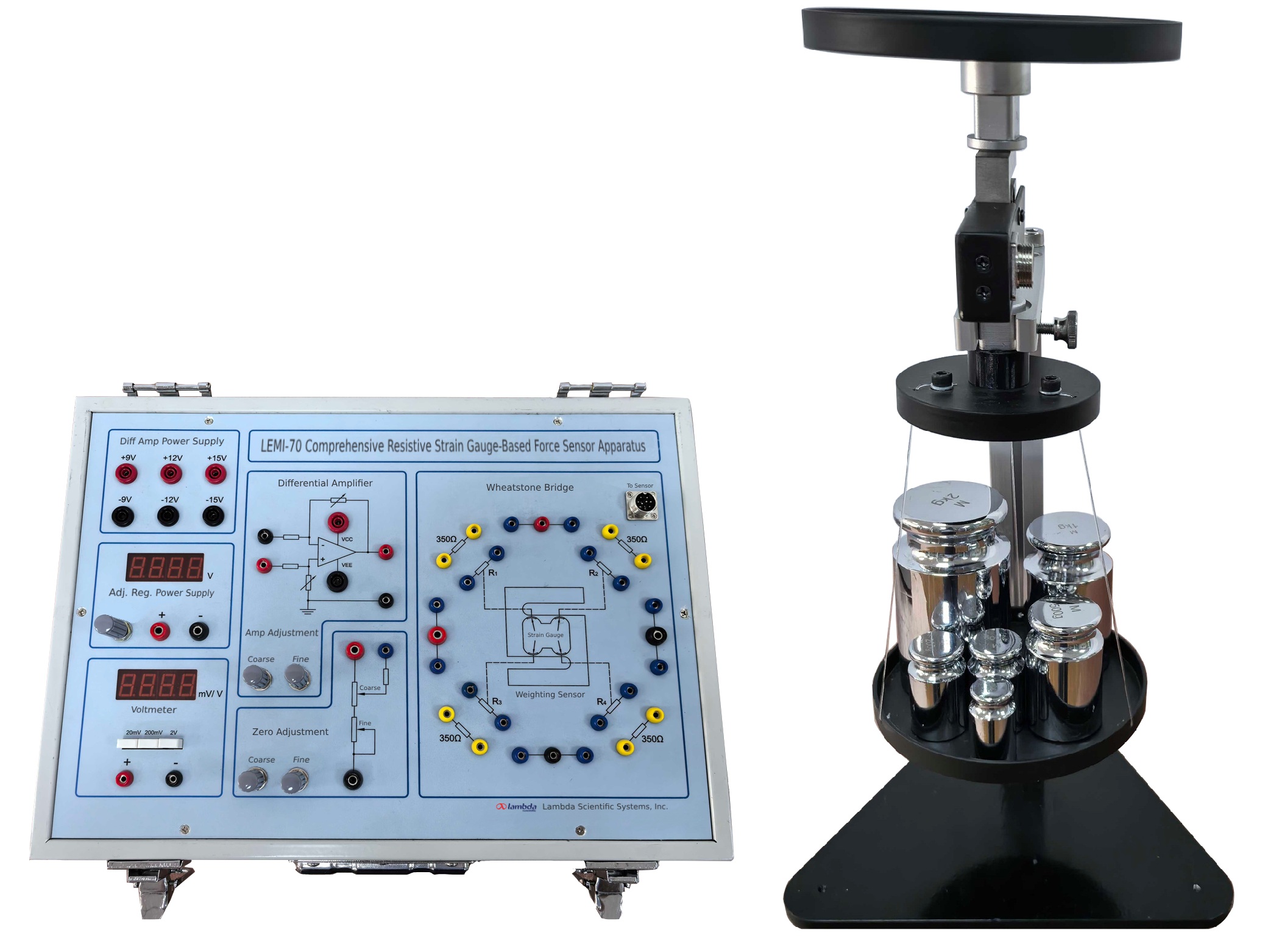
The LEMI-70 Comprehensive Resistive Strain Gauge-Based Force Sensor Apparatus features a bidirectional (tension and compression) weighting sensor with four individually accessible strain gauges and an adjustable bridge excitation voltage. The apparatus allows users to measure and analyze the relationship between tensile/compressive forces and bridge output signals under quarter-bridge, half-bridge, and full-bridge configurations, and to calculate sensitivity.
Additionally, the system includes a built-in differential amplifier with adjustable gain, enabling amplification and calibration of bridge output signals. Users can construct and calibrate a functional electronic scale for force measurement purposes. Through hands-on experiments, students will gain a comprehensive understanding of the operating principles of resistive strain gauges and electronic weighing systems. Experimental objectives include:
1) Understand the working principles of resistive strain gauges and weighting sensors.
2) Measure and compare the performance and sensitivity of quarter-bridge, half-bridge, and full-bridge configurations.
3) Construct and calibrate an electronic weighing scale.
The included instruction manual offers everything you need for a successful lab experience:
- Clear explanations of principles
- Step-by-step procedural guides
- Sample experimental results for reference
Please click Experimental Theory and Experimental Contents to find more information about this apparatus.
Main Specifications
| Description | Specifications |
| Adjustable Regulated Power Supply | 0–14V continuously adjustable, 3½-digit digital display, display precision of 0.01V, with short-circuit protection |
| Digital Voltmeter | 3½-digit digital display with three selectable ranges: -19.99 mV to 19.99 mV, -199.9 mV to 199.9 mV and -1.999 V to 1.999 V |
| Differential Amplifier Power Supply | Three sets of dual-output supplies: ±9V, ±12V, and ±15V |
| Weighting Sensor | Dual-purpose for tension and compression; contains four 350Ω strain gauges; maximum capacity: 5 kg |
| Weight Trays | Two trays (one for tension, one for compression), each with a diameter of 14 cm |
| Calibration Weights | One 100g, two 200g, one 500g, one 1kg, and one 2kg. |
| Support Stand | Triangular base, height: 33 cm |
Part List
| Description | Qty |
| Main Electric Unit | 1 |
| Mechanical Platform | 1 (Includes stand, sensor, and 2 weight trays) |
| Calibration Weight | 6 (100g x1, 200g x2, 500g x1, 1kg x1, 2kg x1) |
| Aviation Cable | 1 |
| Cable | 1 |
| Shielded Banana Plug Cable | 2 (1 red, 1 black) |
| φ4 Banana Plug Cable | 4 (2 red, 2 black) |
| φ3 Banana Plug Cable | 14 (2 red, 2 black, 10 blue) |
| Power Cord | 1 |
| User Manual (CD) | 1 |
Schematic of an electronic scale circuit
Configurations of two measurement modes
Weighting sensor mass–voltage (m–U) curves under different bridge excitation voltages (half-bridge)
Relationship curve between slope K and bridge excitation voltage (half-bridge)
