

Amplitude versus frequency

Phase versus frequency
Features
Good system stability and small amplitude attenuation at free oscillation
Obvious resonant effect and clear physical phenomena
Rich experiment contents, easy operation and high measurement accuracy
Introduction
Forced vibration resonance is a phenomenon that has garnered significant attention in engineering and scientific disciplines, including machinery, construction, and acoustics. It can be either beneficial or detrimental, depending on the context. Many electroacoustic devices are designed based on resonance principles, and in the field of microscience, resonance serves as a crucial research tool—such as in nuclear magnetic resonance (NMR) for material structure analysis. Forced vibration is characterized by natural phase-frequency and amplitude-frequency responses, making it essential for understanding dynamic systems.
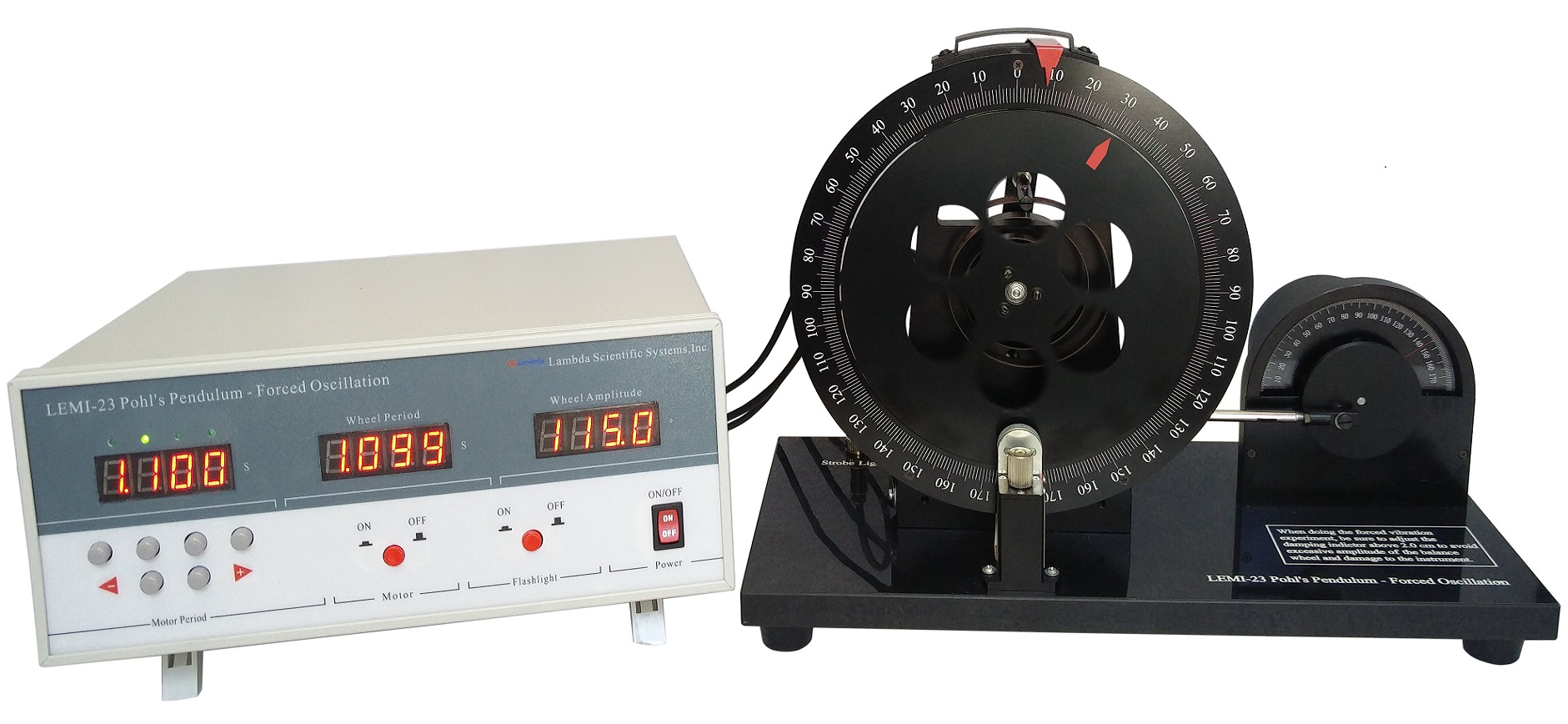
The LEMI-23 Pohl's Pendulum is a state-of-the-art apparatus designed to study forced oscillations through resonance. This system features a mechanical resonant vibration unit combined with an electric control unit for precise experimentation. The setup includes a copper circular balance wheel mounted on a rack with marked angle scales on its outer ring. One end of a spring is attached to the wheel's shaft, and the other end is fixed to the rack. The balance wheel swings freely in response to spring force.
A pair of permanent magnets positioned beneath the rack creates electromagnetic damping when the balance wheel cuts the magnetic field lines. The damping intensity can be adjusted by moving the magnets. To induce forced vibration, an eccentric wheel is mounted on the motor shaft, which drives the balance wheel via a connecting-rod mechanism.
A plastic glass wheel with engraved marker lines, mounted on the motor shaft, rotates in sync with the motor. The phase difference (φ) between the balance wheel and the external torque is determined using a stroboscopic method. As the black line on the inner side of the balance wheel passes through a reflective photoelectric gate, a flash is triggered, allowing easy measurement of the phase difference with an accuracy of less than 2°.
Using the LEMI-23 Pohl’s Pendulum, students can conduct the following experiments:
1. Determine Amplitude-Frequency and Phase-Frequency Characteristics: Measure the response of forced vibrations, identifying resonance behaviors.
2. Study the Influence of Damping Coefficient: Investigate how different damping coefficients affect forced vibrations and observe the resonant vibration phenomenon.
3. Learn the Stroboscopic Method: Use the stroboscopic technique to measure dynamic quantities of moving objects and explore their behavior under forced oscillations.
This apparatus provides an engaging way to investigate and quantify the amplitude-frequency and phase-frequency characteristics of forced vibration, examine the effects of damping on vibration behavior and understand the underlying principles of resonance, and master the stroboscopic method, a valuable technique in dynamic measurement, enhancing understanding of phase relationships in oscillatory systems.
The detailed instruction manual includes experimental configurations and step-by-step setup instructions, in-depth explanations of the underlying principles of forced oscillations and resonance, examples of experimental results for analysis and comparison, and guidance on data processing and error analysis.
Please click Experiment Theory and Contents to find more information about this apparatus. The LEMI-23 Pohl’s Pendulum offers an excellent platform for studying the mechanics of forced oscillations and resonance, combining advanced measurement techniques with practical applications in vibration analysis.
Specifications
| Description | Specifications |
| Spring stiffness coefficient K | Variation of free vibration period:<1% |
| Time measurement | Accuracy: 0.001 s; error of period: 0.2%; 4-digit display |
| System damping | Amplitude attenuation<2% without electromagnetic damping |
| Amplitude measurement | Error: ± 1゜ |
| Motor rotational speed | Range: 15 ~ 50 r/min; period adjustable: 0.2 ~ 4 s |
| Phase difference measurement | Error < 2゜when phase difference between 40 ~ 140゜ |
Parts List
| Description | Qty |
| Main unit | 1 |
| Electric control unit | 1 |
| Wire and cable | 3 |
| Manual | 1 |
Amplitude versus frequency
Phase versus frequency
