

Examples of electrode patterns and corresponding electrostatic field simulations
(click figure to enlarge)
Features
Intuitive and clear configuration
Convenient operation
Stable and reliable measurements
Introduction
In engineering applications, understanding the electric field distribution of an electrode system is often crucial for studying the motion of electrons or charged particles within an electric field. For instance, analyzing the electric field distribution in the electrodes of an oscilloscope tube is essential for understanding electron beam focusing and deflection.
Electric field distribution can be determined through either mathematical analysis or experimental simulation. Mathematical analysis is typically used for simple electrode systems, while experimental simulation is more suitable for complex systems.
The simulation method involves substituting a difficult-to-implement or hard-to-measure physical process with an easier-to-implement or more measurable process. This approach requires a one-to-one correspondence between the two physical processes, including similar mathematical expressions and boundary conditions. For stable physical fields, once the differential equations and boundary conditions are established, the solution is unique. Since the mathematical expressions and boundary conditions of a steady current field are identical to those of an electrostatic field, steady current fields can be used to simulate electrostatic fields.
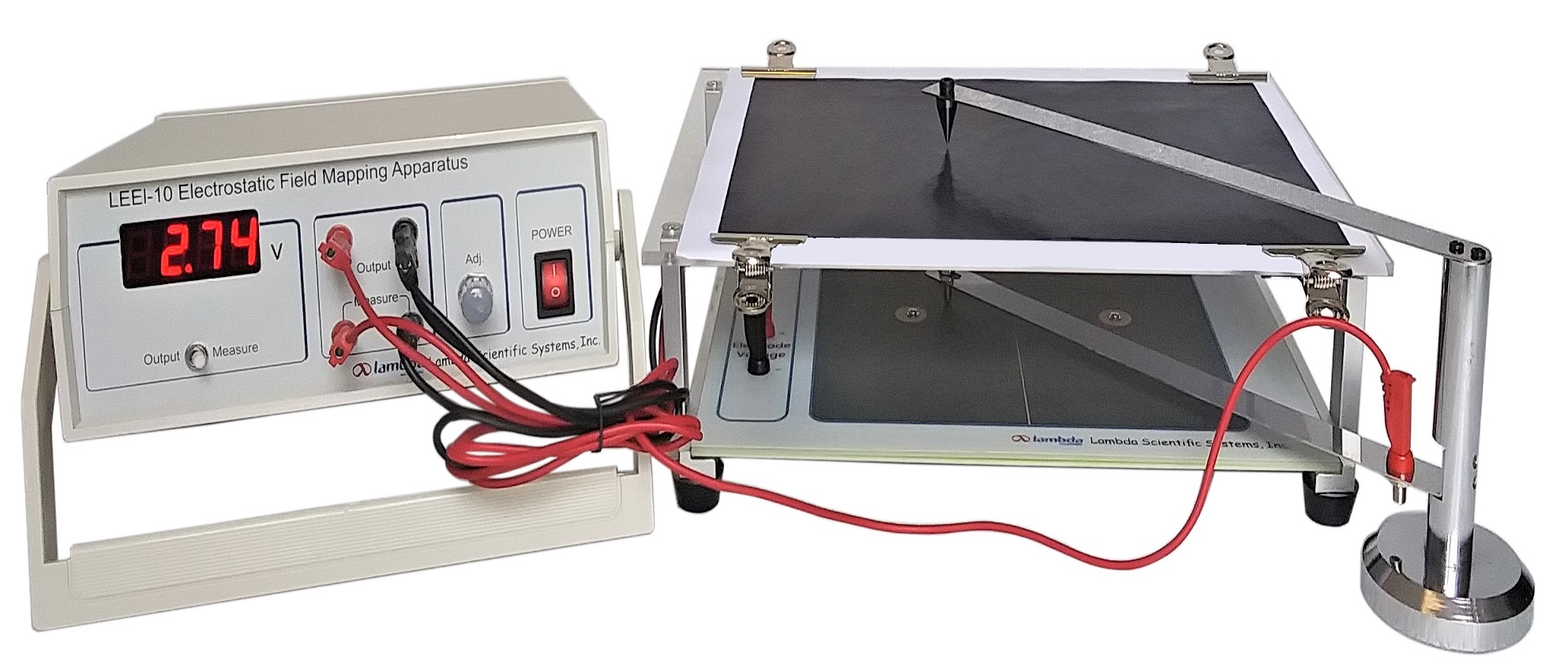
This experimental apparatus is designed with an intuitive and clear configuration. It features a two-level structure that allows precise positioning on a plane and synchronized point sampling. The apparatus is easy to operate, and its measurement data are stable and reliable.
Using this apparatus, students can:
1. Learn to study electrostatic fields using the simulation method.
2. Enhance their understanding of electric field strength and potential concepts.
3. Map equipotential lines and electric field lines for two electrode patterns: a coaxial cable and a pair of parallel wires.
The instruction manual includes experimental configurations, theoretical principles, and step-by-step instructions. For more details, please click on Experiment Theory and Contents to explore this apparatus further.
Specifications
| Description | Specifications |
| Power supply | 0 ~ 15 VDC, continuously adjustable |
| Digital voltmeter | range -19.99 V to 19.99 V, resolution 0.01 V |
| Parallel wire electrodes | Electrode diameter 15 mm Distance between electrodes 95 mm |
| Coaxial electrodes | Diameter of central electrode 15 mm Width of ring electrode 10 mm Inner diameter of ring electrode 150 mm |
Parts List
| Item | Qty |
| Main electric unit | 1 |
| Conductive glass and carbon paper support | 1 |
| Probe and needle support | 1 |
| Conductive glass plate | 2 |
| Connection wire | 4 |
| Carbon paper | 100 sheets A4 size |
| Coordinate paper | 100 sheets A4 size |
| Paper clamps | 4 |
Optional conductive glass plate: focusing electrode & non-uniform field electrode | each one |
| Instruction manual | 1 (Electronic version) |
Examples of electrode patterns and corresponding electrostatic field simulations
(click figure to enlarge)
