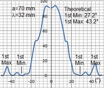
Diffraction distribution of single slit

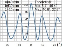
Interference of double slits

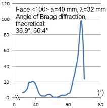
Bragg diffraction

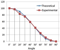
Malus' law
Features
Advanced microwave study
Comprehensive experimentation
Enhanced features
Quantitative analysis
Introduction
Microwaves and light waves, as electromagnetic waves, exhibit shared phenomena such as reflection, refraction, polarization, interference, and diffraction. However, due to the significantly longer wavelength of microwaves (approximately 4 orders of magnitude larger than visible light), their experimental setups and observed phenomena differ.
The LEEI-62 Microwave Experimental System provides an advanced platform for studying the interference, diffraction, and polarization of microwaves. This system incorporates a microwave transmitter with a variable attenuator, a microwave detector with a meter display, transmitting and receiving horns, and various accessories, such as single slits, double slits, a beam splitter, and a crystal model. It enables quantitative analysis and in-depth exploration of multiple wave phenomena.
Using this apparatus, students can perform the following experiments:
1. Verify the Law of Reflection: Investigate the reflection properties of electromagnetic waves.
2. Measure Intensity Distribution of Single-Slit Diffraction: Analyze how microwaves diffract through a single slit.
3. Measure Intensity Distribution of Double-Slit Interference: Examine interference patterns created by double slits.
4. Determine Microwave Wavelength: Use a Michelson interferometer to measure the wavelength of microwaves.
5. Study Polarization: Observe polarization properties and verify Malus' Law.
6. Verify Bragg Diffraction: Study diffraction patterns using a crystal model.
The instruction manual provides detailed explanations of experimental setups, theoretical principles, step-by-step procedures, and sample results to ensure precise and reliable outcomes for advanced educational applications. Please click Experiment Contents and Results to find more information about this apparatus.
Specifications
| Item | Specifications |
| Frequency | Range: 8.6~9.6 GHz; draft: ± 5×10⁻⁴/15-min; display error: ±40 MHz |
| Output power | >20 mW |
| Working voltage | DC 12 V |
| Wave form | Equal amplitude |
| Internal modulation | Square-wave at 1 kHz |
| Output waveguide dimensions | Inner: 22.86 mm × 10.16 mm |
| Standing-wave coefficient | ≤ 1.2 (synthesis voltage) |
| Output microwave wavelength | λ =32.02 mm (factory preset) |
| Horn antenna | Gain ~ 20 dB; lobe width H 200 & E 160 |
Part List
| Description | Qty |
| 3-cm solid state microwave signal source | 1 |
| Base | 1 |
| Platform | 1 |
| Fixed arm | 1 |
| Horn antenna | 2 |
| Variable attenuator | 1 |
| Crystal detector | 1 |
| Indicator meter | 1 |
| Video cable | 1 |
| Reflection plate (aluminum) | 1 |
| Single-slit plate (slit width adjustable) | 1 |
| Double-slit plate (slit width adjustable; barrier=50 mm) | 1 |
| Partial transparent plate (glass) | 1 |
| Simulated crystal with support | 1 |
| Translation stage | 1 |
| Support base | 1 |
| Support post | 4 |
| Module piece | 1 |
| Screws and nuts | 1 set |
| Instruction manual | 1 |

Diffraction distribution of single slit

Interference of double slits

Bragg diffraction

Malus' law